
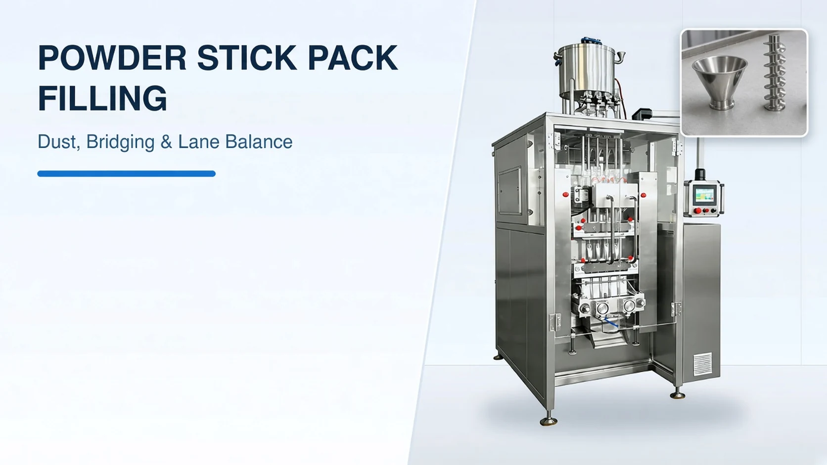
At a glance
Swipe to compare all columns.
| Review area | Bring to the discussion | Decision to record |
|---|---|---|
| Hopper flow and dosing | Powder sample, loose and tapped bulk density, Carr Index, and Hausner Ratio | Vertical servo auger geometry, wedge hopper slope, and agitation setup |
| Dust and cross-seal protection | Stick drawing, laminate roll stock, and ambient humidity profile | Filling tube containment, dust aspiration port, and jaw cleaning schedule |
| Multi-lane weight balance | Target dose, active lane count, and net-content inspection protocol | Lane-labeled sampling, checkweigher feedback loop, and per-lane reject chute |
Auger vs. Volumetric Cup Dosing and Multi-Lane Vertical Packaging Principles
Food, pharma, and chemical companies typically pack powder products in sachets of a few dozen grams or pouches of a few hundred grams to a few kg, whereas bulk filling in 25 kg bags or supersacks is a separate category. In an auger filling machine, the powder is dosed toward the sachet, pouch, or stick with an auger, or Archimedes screw, that sits partly inside a hopper and partly inside a filling tube. An auger filling machine is volumetric: dosing is based only on the number of rotations of the auger, which delivers a volume corresponding to a weight via the material bulk density. Engineers comparing net weight vs volumetric filling workflows should evaluate how powder flow shifts before locking the dosing architecture.
Auger hoppers are typically cone-shaped when there is only 1 Auger for 1 filling head, and wedge-shaped when there are several augers across several filling heads. Auger dosing into formed packs is sequential rather than continuous: the machine forms and positions a pack, the auger runs to dose the product into the open pack, and the pack is closed and moved away. For precise volumetric dosing and a sharp stop, the auger fits tightly in the filling tube and is driven by a servomotor with a settable rotation count, so a slightly bent auger can cause metal-to-metal contact across the narrow gap. Compared with auger filling, a volumetric cup filler is passive because powder must flow by itself in and out of the rotating cup, losing accuracy if the powder is cohesive, does not flow well, or compacts inside the cup.
On a multi-lane VFFS machine, vertical auger filling inside an enclosed wedge hopper contains airborne dust, uses independent servomotors for precise screw rotation, and scales across multiple parallel lanes to multiply output. Intermittent-motion VFFS lines typically run 30 to 80 cycles per minute per lane, while high-speed continuous lines reach 100–200+ cycles per minute. As we emphasize on our Powder Filling Machines and Dosing Methods page, an on-target net weight never compensates for powder trapped in the cross seal, so our factory acceptance trials validate hopper flow, auger dosing and seal integrity together.
Bulk Density, Carr Index, and Hopper Bridging vs. Ratholing
Loose bulk density is measured after powder is poured into a container without settling in its aerated state, whereas tapped bulk density is measured after mechanical tapping achieves maximum particle packing. Engineering rules of thumb use loose bulk density for silo/hopper volume sizing, tapped bulk density for feeder motor power calculations after a stop, and agitation or vibration when a high Carr Index threatens volumetric dosing accuracy. A weighing hopper holding 500 kg of powder with a loose density of 0.34 kg/l requires 1470 Liters of useful volume, and designing a hopper using tapped density for a product with a Carr Index of 20% leaves the hopper 20% undersized. Structured sample testing on production powder lots clarifies how hopper geometry and agitation affect flow before machine fabrication.
Upon opening an obstructed hopper, an empty cone tip above the discharge valve with powder blocked above in a bridge indicates arching or bridging, whereas an open central funnel from top to bottom with stagnant material on the sides indicates ratholing or channelling. Total inter-particle adhesion force F equals Van der Waals force Fv plus capillary moisture force Fc plus electrical force Fe plus electrostatic force Fes, and capillary forces can be kept at a reasonable level if process relative humidity is kept below 65 % RH. Arching occurs when a cohesive powder is stored in a hopper whose cone walls are too flat or whose outlet is smaller than the critical outlet diameter determined by powder testing. Ratholes form in non-mass-flow hoppers with too small an outlet and are avoided by designing the outlet diameter larger than the rathole critical diameter determined by shear cell testing, which is usually larger than the arching diameter.
The Carr Index is calculated from tapped bulk density ρtapped in kg/m3 and loose bulk density ρbulk in kg/m3 as the difference ρtapped minus ρbulk divided by ρtapped multiplied by 100, and relates to the Hausner Ratio H as H equals 100 divided by the difference 100 minus the Carr Index. The Hausner Ratio H is calculated directly as the ratio of tapped bulk density to loose bulk density: H = ρtapped/ρbulk. In the Carr Index and Hausner Ratio flowability table, Excellent / Very Free Flow corresponds to Hausner Ratio 1.00 - 1.11 and Carr's Index <10, while Good / Free Flow corresponds to Hausner Ratio 1.12 - 1.18 and Carr's Index 11-15. In the Carr Index and Hausner Ratio flowability table, Fair flow corresponds to Hausner Ratio 1.19 - 1.25 and Carr's Index 16-20, while Passable flow corresponds to Hausner Ratio 1.26 - 1.34 and Carr's Index 21-25.
In the Carr Index and Hausner Ratio flowability table, Poor Flow or Cohesive corresponds to Hausner Ratio 1.35 - 1.45 and Carr's Index 26-31, Very Poor Flow or Very Cohesive corresponds to 1.46 - 1.59 and Carr's Index 32-37, and Approximatively no flow is > 1.60 and Carr's Index > 38. A powder with a loose bulk density of 600 kg/m3 and a tapped density of 660 kg/m3 has a Carr Index of 9.1 and a Hausner Ratio of 1.1, classifying it as probably free flowing. Generally, a powder with a Carr Index of less than 10% forms a flat pile with an angle of repose between 25 and 30 degrees, whereas a cohesive powder with a Carr Index above 32% forms an angle greater than 55 degrees.
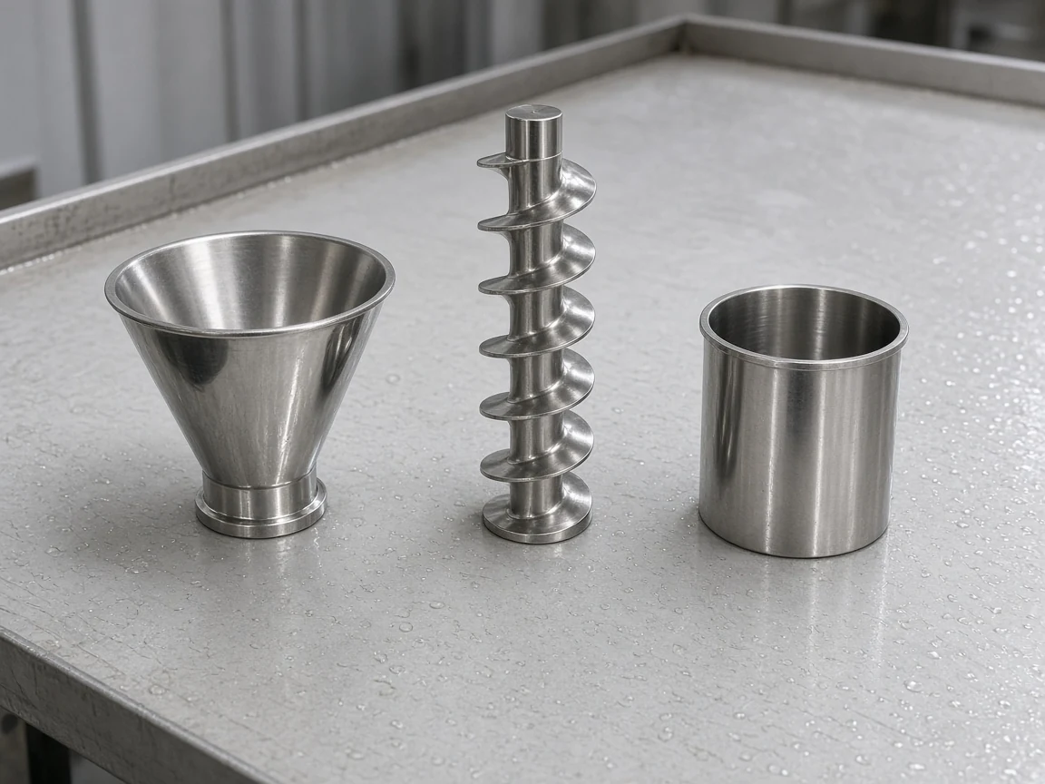
Hopper Level Stability, Dust Aspiration, and Seal Contamination
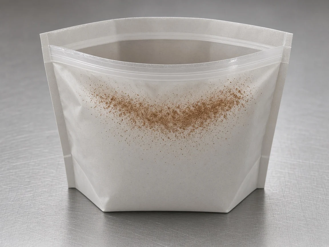
Irregular powder flow in the hopper directly above the filling heads causes strong deviation in packaged weight; it is addressed by making the cone or wedge hopper slope steep enough and adding agitators or small vibrators to break bridging or ratholes. Net weight variability in volumetric powder filling is typically related to product flow: irregular filling can be due to cohesive powders or bad flow in the buffer hopper, while another possible issue is a fluctuating product level above the dosing system where flow changes with product height; flowability issues are addressed by formulation or discharging aids, and fluctuating hopper level can be improved by changing hopper refilling control. Pack micro-leakages or spillages occur when powder gets trapped between the 2 sides of the packaging material because falling product generates dust that has not settled when the sealing jaws close, requiring a dust aspiration system.
A vertical stick-pack machine uses a longitudinal fin/lap sealing bar operating once per cycle and heated corrugated horizontal jaws (or ultrasonic horns) operating twice per pouch to close the bottom and top cross seals. As detailed in our Auger vs Volumetric Cup Filling guide, we tag sampled sticks with the preceding machine event so hopper-refill and restart packs are evaluated separately from steady-state production, recording both seal-zone cleanliness and tare-corrected net mass.
Sealing Jaw Maintenance, Kevlar and Brass Cleaning, and Carbon Impressions
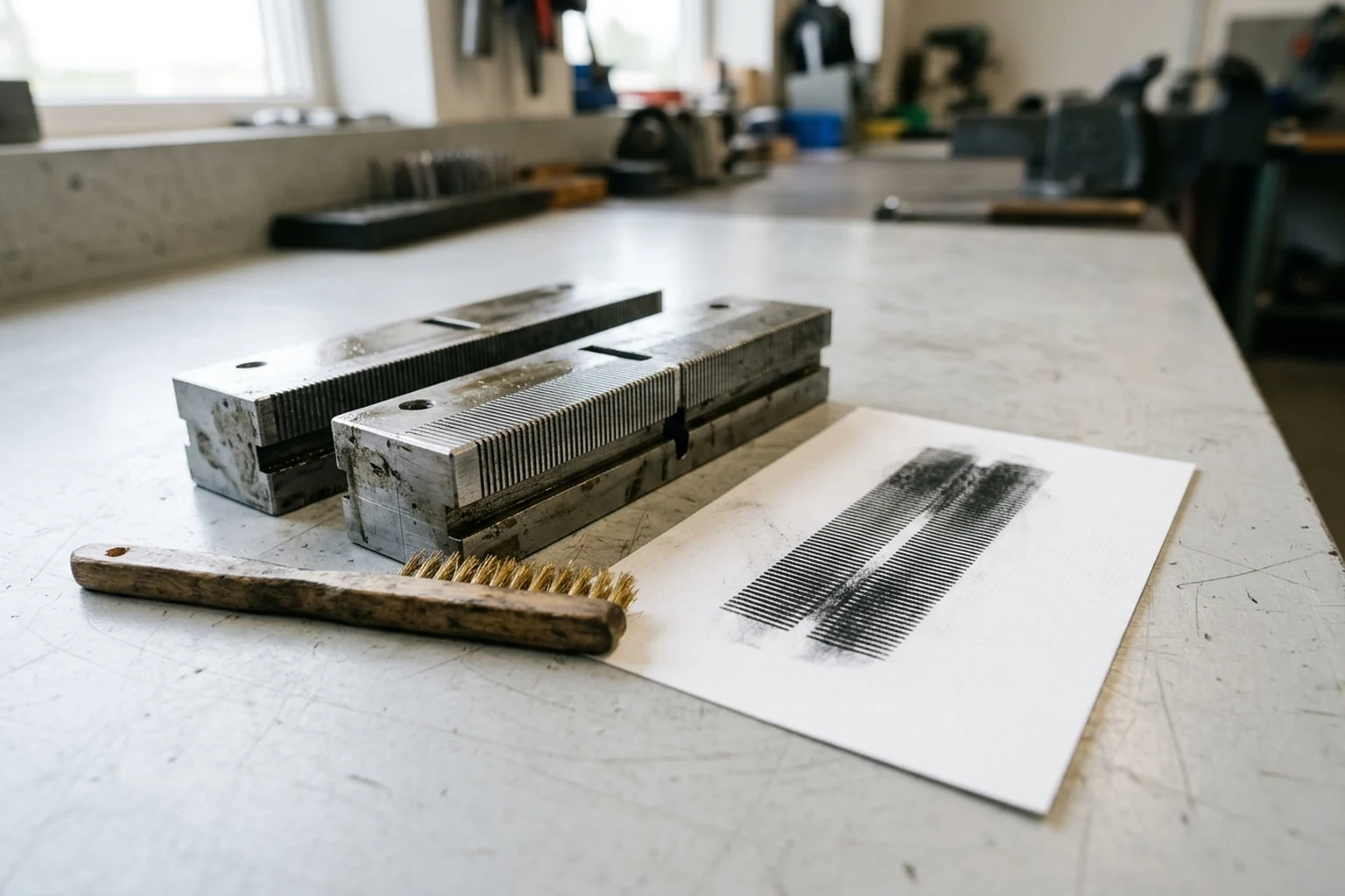
Product build-up on crimpers and sealing jaws degrades seal quality and productivity by causing jaw pressure and alignment problems, poor heat transfer, and knife-slot cutting issues. Hard metal objects such as scissors or screwdrivers can damage sealing jaws or knives; Kevlar scrapers matched to the jaw serrations and brass or nylon brushes cleaned in the direction of the serrations remove buildup safely.
On cold or hot reciprocating sealing jaws, carbon paper must be used for installation and adjustments because carbonless paper is not properly activated, whereas hot rotary jaws require carbonless paper because carbon paper melts; impressions should be taken once or twice a week. In a Greener Corporation troubleshooting case where nine of ten packages failed a seal quality test, carbon impressions revealed extensive sealing jaw product contamination, and cleaning the jaws reduced the failure rate to zero.
Multi-Lane Stick-Pack Machine Envelopes, Per-Lane Reject, and Checkweighing
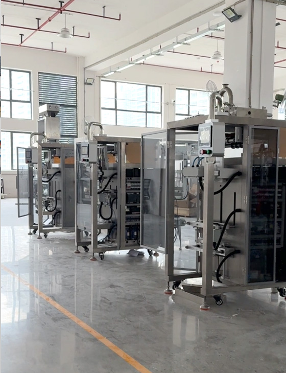
Our multi-lane powder stick-pack configurations combine 316L stainless-steel contact parts, tool-free swivel auger disassembly, contra-rotational hopper agitation, and individual servo auger trim across 2 to 12 lanes (25 to 70 cycles/min, 0.5 to 50 g fill range, 15 to 60 mm stick width, and 50 to 200 mm stick length, up to 620 mm maximum reel width).
Across multi-lane stick widths on a 300–620 mm web, typical per-machine output scales from 140 sticks/min on wide 4-lane formats (up to 60 × 160 mm) and 210 sticks/min on mid-width 6-lane formats (up to 45 × 160 mm) to 280–720 sticks/min on narrow 8- to 12-lane nutraceutical and instant-coffee sticks (17–35 × 160 mm).
To prevent a single out-of-tolerance lane from scrapping an entire multi-lane discharge row, we equip multi-lane powder lines with individual lane exit chutes, per-lane reject diverters, and closed-loop checkweigher feedback to each servo auger—reducing false-reject product and film waste by up to 80% on a 5-lane configuration compared with full-row rejection. Total output equals cycles per minute multiplied by active lanes, and during FAT we log tare-corrected weights by individual lane number and timestamp so opposing high/low lane drift is never masked by a combined row average.
Prepackage Metrology, Tolerable Deficiencies, and Checkweigher Verification
For prepackages, the average actual quantity of product shall be at least equal to the nominal quantity, a homogenous group shall contain no more than 2.5 % of packages having T1 errors, and no prepackage shall have a T2 error. For prepackages, a T1 error is a deficiency greater than the applicable tolerable deficiency T but not greater than 2T where Qnom – 2T ≤ Qi < Qnom – T, and a T2 error is a deficiency greater than twice the applicable tolerable deficiency where Qi < Qnom – 2T. Under Table 1, the tolerable deficiency T for nominal quantity Qnom of 0 to 50 g or mL is 9 percent of Qnom, for 50 to 100 g or mL is 4.5 g or mL, and for 100 to 200 g or mL is 4.5 percent of Qnom, with T values rounded up to the next 0.1 of a g or mL for Qnom <= 1 000 g or 1 000 mL. Evaluating filling accuracy and speed together keeps per-lane weight drift and line throughput aligned during commissioning.
Gravimetric net-content testing of packaged goods requires a scale division no larger than 1/6 of the Maximum Allowable Variation, written as MAV/6, for the package size being weighed. Under Table 2-5, the Maximum Allowable Variation MAV for packages labeled by weight is 10 % of labeled quantity for less than 36 g or 0.08 lb or 1.28 oz, 3.6 g for 36 g or more to 54 g, and 5.4 g for more than 54 g to 81 g. Category X applies only to automatic checkweighers used to check prepacked products that are subject to the requirements of OIML R 87, divided into four accuracy classes: XI, XII, XIII, and XIIII. Under Table 3, for Category X checkweighers in the first net-load range covering 0 < m <= 50 000 e for XI, 0 < m <= 5 000 e for XII, 0 < m <= 500 e for XIII, and 0 < m <= 50 e for XIIII, the maximum permissible mean error is ±0.5 e on initial verification and ±1 e on in-service inspection. Under Table 4, for a class designation factor x = 1, the maximum permissible standard deviation for net load m <= 50 g is 0.48 % on initial verification and 0.6 % on in-service inspection, and for 50 < m <= 100 g is 0.24 g on initial verification and 0.3 g on in-service inspection.
Sources
- PowderProcess.net — Powder Small Packs Filling Principles, Bulk Density, Carr Index & Hopper Design
- Greener Corporation — Sealing Jaw Carbon Impressions and Serration Cleaning Guidelines
- International Organization of Legal Metrology — OIML R 87 Quantity of Product in Prepackages & OIML R 51 Automatic Catchweighing Instruments
- National Institute of Standards and Technology — NIST Handbook 133 Checking the Net Contents of Packaged Goods
- Automatic Filling Machine — Multi-Lane Powder Stick-Pack Machine
- Automatic Filling Machine — Powder Filling Machines and Dosing Methods
- Automatic Filling Machine — Auger vs Volumetric Cup Filling
Common questions
Why do multi-lane powder stick-pack machines use servo augers instead of volumetric cups?
Compared with auger filling, a volumetric cup filler is passive because powder must flow by itself in and out of the rotating cup, losing accuracy if the powder is cohesive, does not flow well, or compacts inside the cup. On a VFFS machine, vertical auger filling inside a closed hopper avoids releasing dust, uses servomotors for precise screw activation, and allows several lanes in a single machine to increase capacity.
How do bridging and ratholing differ inside a powder hopper?
Upon opening an obstructed hopper, an empty cone tip above the discharge valve with powder blocked above in a bridge indicates arching or bridging, whereas an open central funnel from top to bottom with stagnant material on the sides indicates ratholing or channelling. Irregular powder flow in the hopper directly above the filling heads causes strong deviation in packaged weight; it is addressed by making the cone or wedge hopper slope steep enough and adding agitators or small vibrators to break bridging or ratholes.
What causes micro-leaks in powder stick-pack cross-seals and how are jaws cleaned?
Pack micro-leakages or spillages occur when powder gets trapped between the 2 sides of the packaging material because falling product generates dust that has not settled when the sealing jaws close, requiring a dust aspiration system. Hard metal objects such as scissors or screwdrivers can damage sealing jaws or knives; Kevlar scrapers matched to the jaw serrations and brass or nylon brushes cleaned in the direction of the serrations remove buildup safely.
Why does each stick-pack lane need its own reject chute and lane-labeled sampling?
Equipping a multi-lane stick-pack machine (up to 620 mm reel width) with individual lane exit chutes and per-lane reject diverters allows the line to reject a single out-of-spec stick without scrapping the entire multi-lane row. On our Multi-Lane Powder Stick-Pack Machine, total sticks per minute equal cycles per minute multiplied by active lanes, and FAT samples are labeled by lane number and collection time so a combined average never hides one lane running heavy while another runs light.
What scale resolution and deficiency rules apply when checking prepackaged powder sticks?
For prepackages, the average actual quantity of product shall be at least equal to the nominal quantity, a homogenous group shall contain no more than 2.5 % of packages having T1 errors, and no prepackage shall have a T2 error. Gravimetric net-content testing of packaged goods requires a scale division no larger than 1/6 of the Maximum Allowable Variation, written as MAV/6, for the package size being weighed.
What to send us
Swipe to compare all columns.
| Item | Why we need it | Example format |
|---|---|---|
| Powder flowability and density profile | Evaluate bridging, ratholing, and head-pressure sensitivity inside the wedge hopper. | Loose and tapped bulk density, Carr Index, Hausner Ratio, and product sample |
| Stick-pack dimensions and reel layout | Align slitting width, active lane count, and vertical filling tube clearance. | Dimensioned stick drawing, reel width, and laminate specification sheet |
| Dust aspiration and jaw maintenance plan | Prevent airborne powder from settling between film layers before the jaws close. | Aspiration hood connection, Kevlar or brass brush routine, and carbon impression schedule |
| Per-lane weight verification and rejection | Keep individual lane drift visible and avoid rejecting entire multi-lane rows. | Lane-tagged sampling log, checkweigher feedback setup, and individual exit chute reject |
We reply within 24 hours.